Why AWS Route Server Simplifies NVA High Availability
In AWS, building high availability for NVAs (network virtual appliances) has traditionally been more complicated than it should be. Before Gateway Load Balancer (GWLB), many of us relied on custom Lambda functions to monitor instance health and reassign Elastic IP addresses between EC2 network interfaces during a failure.
It worked, but failover times were not great and the setup felt fragile. Gateway Load Balancer improved the architecture, yet it can be complex to configure and sometimes feels like overengineering for smaller environments. Introducing GENEVE encapsulation into the data path is powerful, but not every team needs that level of abstraction just to achieve simple and reliable failover.
In April 2025, AWS introduced Route Server to simplify NVA high availability and routing convergence inside a VPC. I have not had the chance to explore it in depth until now, so the best way to understand it is the way I usually learn new features: build a lab, break it, and see how it behaves.
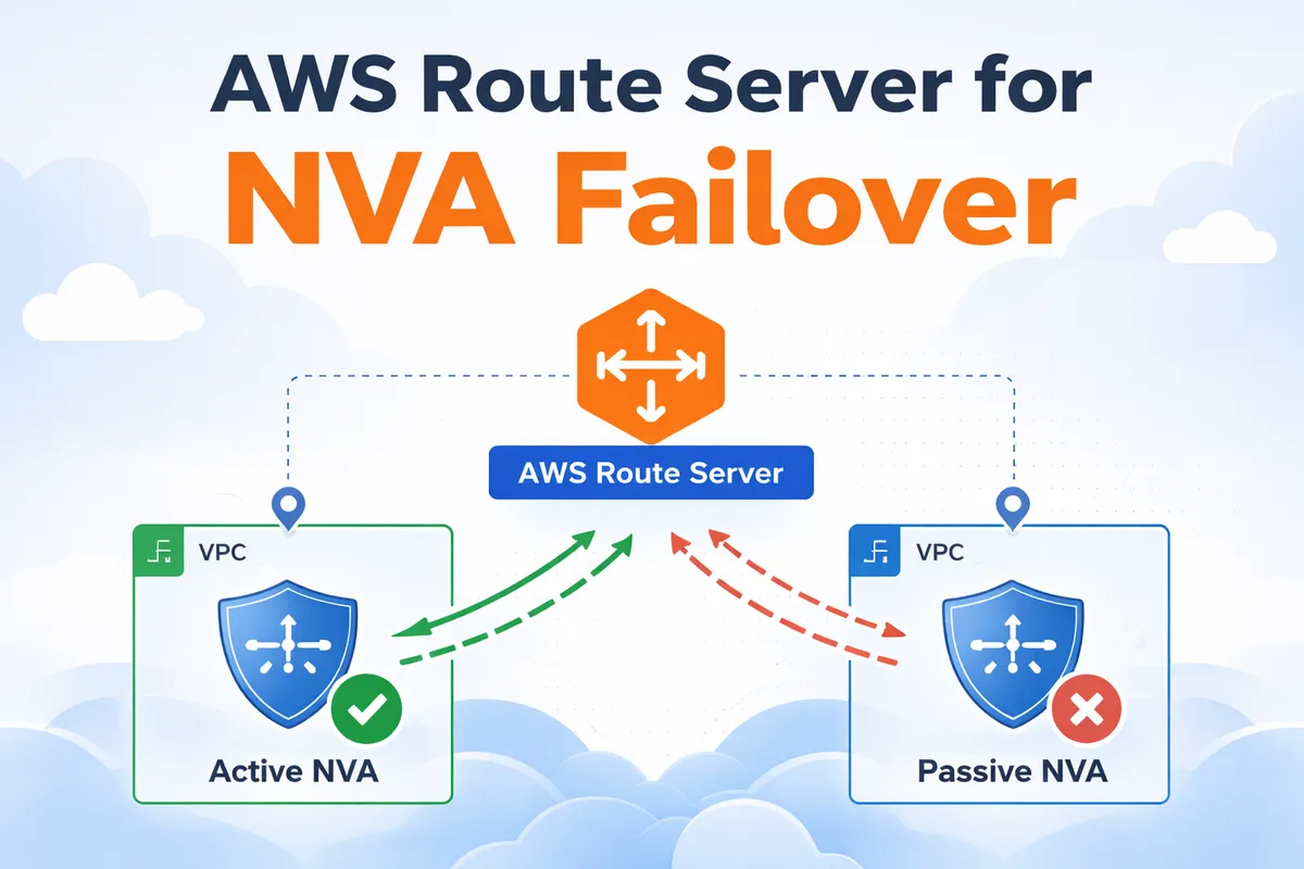
What Is AWS Route Server and Why It Changes NVA Failover
AWS Route Server is conceptually similar to Azure Route Server. It is a managed service that deploys one or more network interfaces into selected VPC subnets, allowing NVAs such as routers or firewalls to establish BGP sessions with them.
Through BGP, NVAs can advertise CIDR prefixes to AWS. When a prefix is received, the Route Server programs the subnet route tables and sets the NVA’s network interface as the next hop. From that moment, traffic matching those routes is forwarded to the appliance based on dynamic routing decisions.
This changes the failover model significantly. Instead of moving Elastic IP addresses or inserting appliances inline with encapsulation, failover becomes a control plane event. If an NVA goes down, its routes are withdrawn, and BGP reconverges to the remaining healthy peer.
NVAs can advertise specific prefixes for traffic inspection between subnets, or even the default route 0.0.0.0/0 to act as centralized internet egress devices. In my lab, I focus on the default route scenario, using the NVAs as outbound internet gateways and observing how BGP handles failover when the active appliance is shut down.
Lab Topology and Traffic Flow
This lab uses a simple hub and spoke design to demonstrate BGP driven NVA failover with AWS Route Server.
The environment includes:
- Workload VPC
- One private subnet
- One EC2 instance generating outbound traffic
- A static default route pointing to the Transit Gateway
- Hub VPC (two Availability Zones)
- Two public subnets hosting one NVA each with a public IP
- Two private subnets hosting the Transit Gateway attachment network interface and one Route Server endpoint per AZ
- Transit Gateway
- Connects the workload VPC and the hub VPC
- Uses a static default route pointing to the hub VPC attachment
It is important to note that AWS Route Server does not propagate routes between VPCs or into Transit Gateway route tables. Inter VPC routing in this setup is fully static. The workload VPC sends default traffic to the Transit Gateway, and the Transit Gateway forwards it to the hub VPC.
The dynamic behavior happens inside the hub VPC private subnets. The Transit Gateway network interfaces reside there, and AWS Route Server programs the subnet route tables based on BGP advertisements from the NVAs. Both NVAs advertise 0.0.0.0/0, and BGP best path selection determines which one becomes active.
Traffic from the workload flows through the Transit Gateway into the hub private subnet, is forwarded to the active NVA, NATed, and then sent to the internet. If the active NVA fails, its BGP session drops, the default route is withdrawn, and traffic shifts to the remaining appliance after convergence.
Transit Gateway is not just a scalable choice here, it is what makes centralized egress possible. With VPC peering, the workload VPC can only point routes to the peering connection itself, not to a specific NVA interface in the hub VPC. In addition, peering does not support transitive or edge to edge routing, so the hub VPC cannot act as a shared internet exit for other VPCs.
With Transit Gateway, the workload sends 0.0.0.0/0 to the TGW, the TGW forwards it to the hub attachment, and once traffic arrives on the hub side TGW network interface, the subnet route table, programmed by Route Server, can steer it to the active NVA.
The architecture is shown in the diagram below.
NVA Configuration and BGP Peering
Both NVAs are small Ubuntu instances that install FRR during provisioning and enable IP forwarding and NAT to act as simple internet gateways. This is just to demonstrate the setup, however in production you could use actual virtual routers or firewall appliances.
Each NVA establishes an eBGP session with its local Route Server endpoint. The session uses ebgp-multihop and disable-connected-check because the peer is not directly connected in a traditional router-to-router design.
Both NVAs advertise the default route, 0.0.0.0/0, but with different MED values. NVA1 sets a lower metric of 10, while NVA2 sets a higher metric of 100. Since both advertise the same prefix, AWS Route Server applies BGP best path selection and prefers the route with the lower MED. As a result, NVA1 is installed as the active next hop in the hub private subnet route table.
The network 0.0.0.0/0 statement originates the default route, while the outbound route map ensures that only this prefix is advertised and sets the metric. The inbound route map denies all routes, as the NVAs do not need to learn anything from the Route Server in this design.
If the primary NVA fails, its BGP session drops, the preferred default route is withdrawn, and the Route Server selects the remaining path from NVA2.
router bgp 65101
 neighbor 10.0.10.72 remote-as 65000
 neighbor 10.0.10.72 ebgp-multihop 2
 neighbor 10.0.10.72 disable-connected-check
 neighbor 10.0.10.72 timers 10 30
 !
 address-family ipv4 unicast
  network 0.0.0.0/0
  neighbor 10.0.10.72 route-map RS-IN in
  neighbor 10.0.10.72 route-map RS-OUT out
 exit-address-family
exit
!
ip prefix-list DEFAULT_ONLY seq 5 permit 0.0.0.0/0
!
route-map RS-IN deny 10
exit
!
route-map RS-OUT permit 10
 match ip address prefix-list DEFAULT_ONLY
 set metric 10
exit
Testing the Setup and Internet Access
The full Terraform code for this lab is provided at the end of the blog post. After running terraform apply, all required resources are created automatically, including the VPCs, Transit Gateway, Route Server endpoints, NVAs, and the BGP peering configuration.
Once the deployment finishes, Terraform outputs the key values needed for testing, such as the public IP addresses of the NVAs and the private IP of the workload EC2 instance. The output will look similar to the following:
aws_vpc_route_server_peer.nva02: Creation complete after 1m35s
aws_vpc_route_server_peer.nva01: Still creating... [01m40s elapsed]
aws_vpc_route_server_peer.nva01: Creation complete after 1m45s
Apply complete! Resources: 42 added, 0 changed, 0 destroyed.
Outputs:
nva01_public_ip = "3.75.170.86"
nva02_public_ip = "3.67.79.244"
route_server_endpoint_subnet01_ip = "10.0.10.37"
route_server_endpoint_subnet02_ip = "10.0.11.26"
route_server_id = "rs-02d3471e5b9146c74"
transit_gateway_id = "tgw-038769faa873d41e0"
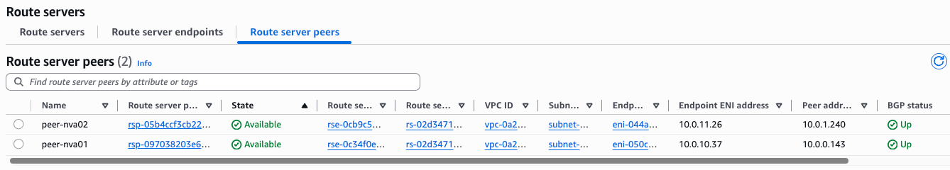
workload_private_ip = "192.168.0.153"After few minutes, you can see the BGP status is Up for both peers. AWS Console is a bit slow, so it could take 5-6 minutes until status goes from Down to Up.
You can verify the BGP status in the NVAs as well:
ip-10-0-0-143# show ip bgp summary wide
IPv4 Unicast Summary (VRF default):
BGP router identifier 10.0.0.143, local AS number 65101 vrf-id 0
BGP table version 1
RIB entries 1, using 192 bytes of memory
Peers 1, using 724 KiB of memory
Neighbor V AS LocalAS MsgRcvd MsgSent TblVer InQ OutQ Up/Down State/PfxRcd PfxSnt Desc
10.0.10.37 4 65000 65101 210 212 0 0 0 00:17:21 0 1 N/A
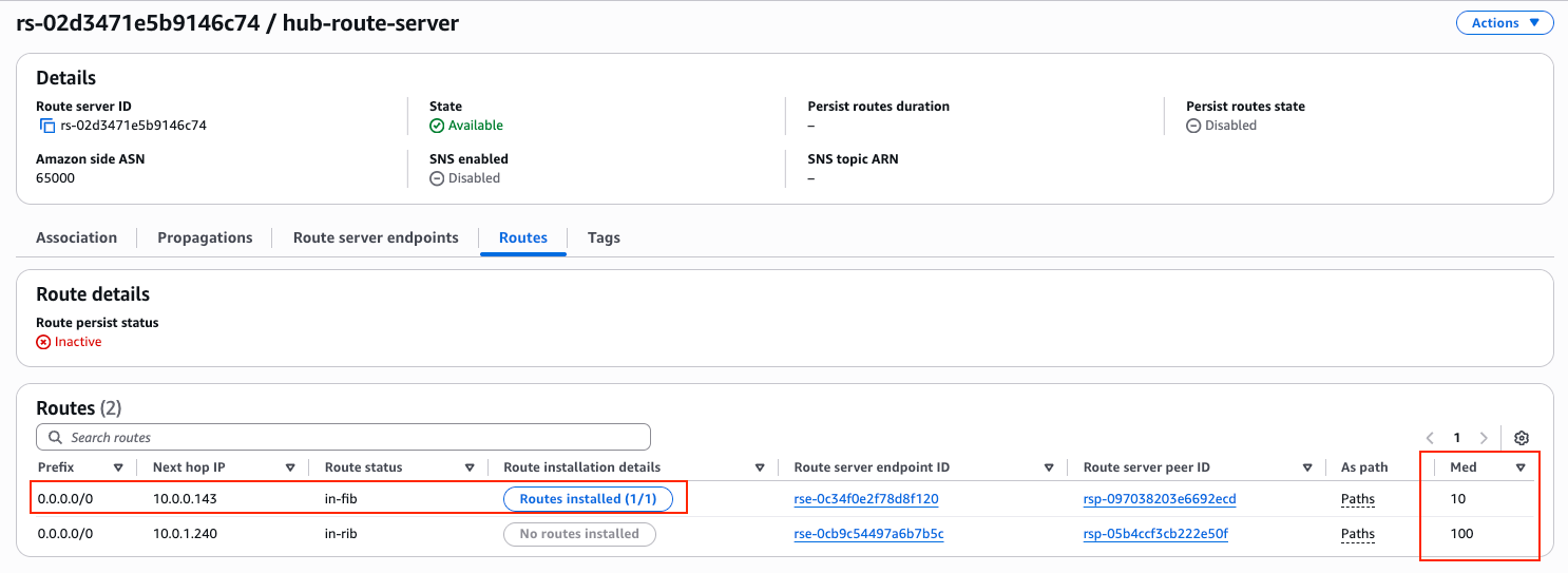
Total number of neighbors 1When checking the AWS Route Server details, it is clear that it received the default route from both NVAs, and it installed the one with the lower MED into the AWS Route Table:
Now let’s test the failover behavior.
First, connect to the workload EC2 instance. Since it does not have a public IP address, I use an SSH jump through one of the NVAs. In this case, I connect through NVA2, which has a public IP, and from there reach the private IP of the workload server.
For reference, Terraform provided the following outputs:
nva01_public_ip = "3.75.170.86"
nva02_public_ip = "3.67.79.244"
route_server_endpoint_subnet01_ip = "10.0.10.37"
route_server_endpoint_subnet02_ip = "10.0.11.26"
route_server_id = "rs-02d3471e5b9146c74"
transit_gateway_id = "tgw-038769faa873d41e0"
workload_private_ip = "192.168.0.153"
Using SSH ProxyJump, I can directly reach the workload instance:
ssh -J [email protected] [email protected]Once logged in, we can verify which public IP address the workload uses for outbound internet traffic. A simple curl icanhazip.com shows the source IP as seen from the internet:
ubuntu@ip-192-168-0-153:~$ curl icanhazip.com
3.75.170.86
The returned IP address matches NVA1’s public IP. This confirms that, in steady state, NVA1 is the active next hop selected by AWS Route Server, and all outbound traffic from the workload VPC is currently passing through it.
Testing the Failover
Let’s trigger a failover by shutting down NVA1. Since we are connected to the workload instance through NVA2 as an SSH jump host, our SSH session should remain active even when NVA1 goes down.
To continuously observe which NVA is being used for outbound traffic, I run the following loop on the workload server. It prints the current timestamp and the public IP address seen from the internet:
ubuntu@ip-192-168-0-153:~$ while true; do echo "$(date '+%Y-%m-%d %H:%M:%S') - $(curl -s icanhazip.com)"; sleep 1; done
2026-02-25 21:41:17 - 3.75.170.86
2026-02-25 21:41:18 - 3.75.170.86
2026-02-25 21:41:19 - 3.75.170.86
2026-02-25 21:41:20 - 3.75.170.86
2026-02-25 21:41:21 - 3.75.170.86
2026-02-25 21:41:22 - 3.75.170.86
2026-02-25 21:41:23 - 3.75.170.86
2026-02-25 21:41:24 - 3.75.170.86
2026-02-25 21:41:25 - 3.75.170.86
2026-02-25 21:41:26 - 3.67.79.244  <-- FAILOVER COMPLETE
2026-02-25 21:41:27 - 3.67.79.244
2026-02-25 21:41:28 - 3.67.79.244
There is no noticeable packet loss or interruption in the loop. The public IP switches from NVA1 to NVA2 within one second, which indicates that the BGP session dropped, the default route was withdrawn, and AWS Route Server selected the backup path very quickly.
This demonstrates the main advantage of using Route Server for NVA high availability: failover is handled by dynamic routing convergence instead of IP reassignment or external automation.
Terraform codes so you can test this setup in your own AWS account
Sometimes the best way to understand a solution is to deploy it yourself and see how it behaves. That is exactly why I packaged this entire architecture into Terraform. With a simple terraform apply, you can build the full environment in your own AWS account, including the VPCs, Transit Gateway, Route Server endpoints, NVAs, and BGP configuration.
Once deployed, you can explore the setup in the AWS Console, inspect the route tables, check the BGP sessions on the NVAs, and even intentionally break parts of the design to better understand how AWS Route Server reacts. Hands on testing makes the control plane behavior much clearer than any diagram. Remember to terraform destroy in order to save costs, once you are finished.
The Terraform code is available below to subscribers only. There is a free tier where you receive email notifications about future technical posts. If you find this content useful and want to support my work, consider subscribing to a higher tier or leaving a tip. It helps me continue building labs and sharing real world cloud networking scenarios.

